GPS and GPRS application kit for M2M FOX based projects
Note: This is a discontinued product. Please evaluate to use the TERRA-M board
FOXGPS and FOXGPRS includes all parts you need to design your own M2M application based on the FOX Board LX
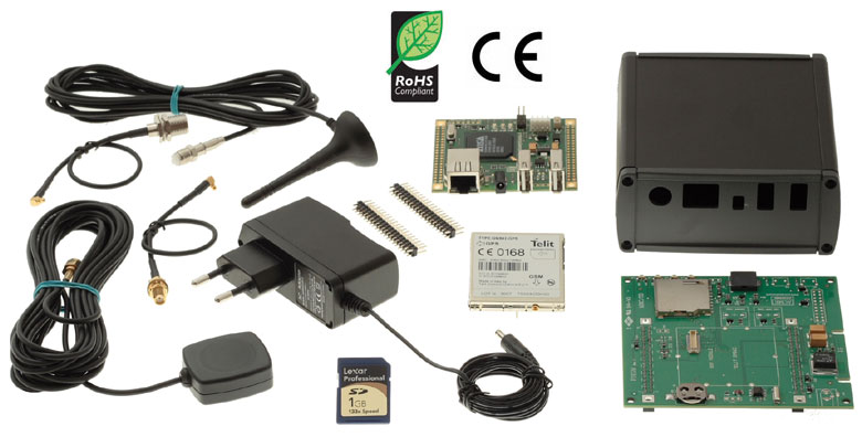
FOXGPS kit parts
The main difference between GPS and GPRS kit is the Telit modem
that includes or not a GPS section.
GPSKIT parts
|
GPRSKIT parts
|
When mounted "as is" with no extra components added, this equipment is fully CE compliants.
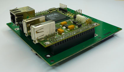
The FOXGM carrier board
|
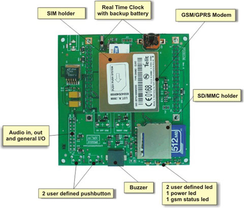
FOXGM carrier board |
|
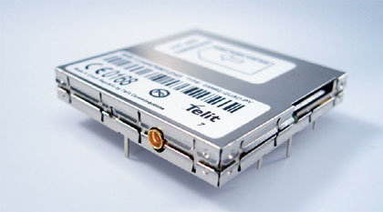
Telit GM862 familyThe GM862 family gets rich of a new generation of modules such as the GM862-GPS, GM862-QUAD-PY and GM862-QUAD, which combine the access to digital communication services in GSM 850, 900,DCS 1800, PCS1900 MHz networks with an additional key feature of the integrated GPS receiver (GM862-GPS only).For more info about Telit GM862 family please visit: |
TEKO Tekal 3 enclosure
FOX GM is designed for the standard extruded aluminium with high quality painted finish enclosure TEKO model Tekal 3. An Acme Systems custom version of this enclosure is available with two perforated ABS panels.
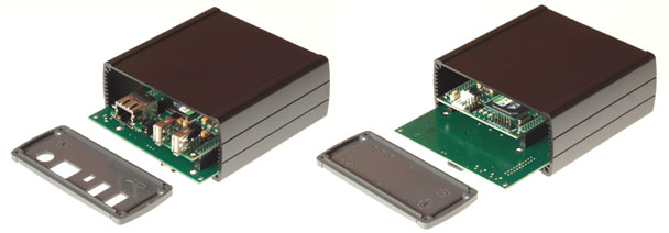
Front and rear view of the Teko enclosure for the FOX GM.
Acme Systems can provides a perforated version of the ABS panel.
Step by step illustrated getting started guide
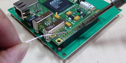
| Weld the 20x2 male pin strips (Code STRIPM2X206MM) in the J6 and J7 placement available on the FOX Board and insert it on the FOXGM board as showed in this figures. |
|
|
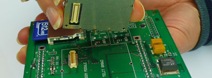
| Any FOXGM has the 50 pins smd socket already soldered and ready to insert a Telit GM862-xxx modem. Insert the modem as showed in the figure. If you have a FOXGMT board your board is complete with a modem already soldered. |
|
|
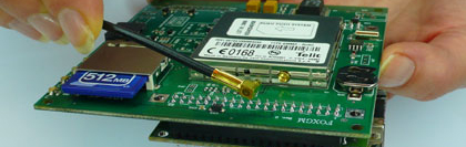
| Before turn on the modem be sure to connect a GSM antenna as showed in this figure. On the Acme Systems eShop (see at the end of this article) you can find a MMCX to FME cable (code MMCX2FME) useful to move the antenna signals on a panel and a GSM Antenna (code GSMANT) with FME connector and 2.5 meter lenght cable. |
|
|
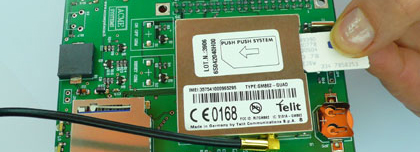
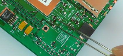
| The Telit GM862-xxx modem has an embedded SIM holder. See the figure to insert the SIM inside it. |
| |
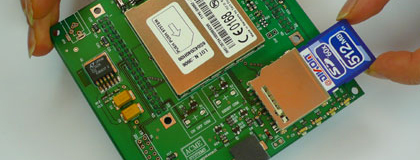
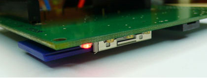
| An SD or MMC card can be used with the FOXGM Board. The figure shows how to insert it. |
|
|
| Insert now the power supply plug to the FOX Board. |
|
|
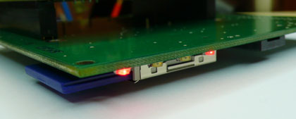
| The L6 led will turn on to indicate the precence of 3.3 volt on the FOXGM Board. |
|
First test with the GSM Modem
|
Now we'll try to turn on the GSM Modem and check if it works well and if there is enough field to do a GSM connection.
It is possible to turn on the Modem by the hardware making a short-cut between the two contacts on S1 placement for
at least 1 second as showed on the figure.
The same effect can be obtained by software sending a 1 second pulse on the PB7 line typing: # setbits -p b -b 7 -s 1 # sleep 1 # setbits -p b -b 7 -s 0 |
|
|
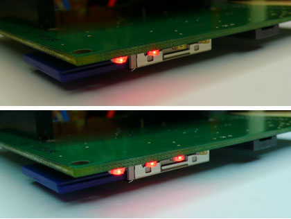
The led L3 will start to blink quite fast to indicate that the modem is turning on and after few seconds more slowly to indicate
that it is registered to the GSM network.
When the Telit modem is turned on, another 1 second pulse on PB7 will turn it off. Now you can comunicate with it on /dev/ttyS2 serial line using the AT command set.
If you are using a standard flash image probably this example will not work because PB7 line is defined as input by default. Use an image available on the download section of this article or see How to set PB6 and PB7 line with FOXGM |
|
The user defined led L4 and L5
The others two leds L4 and L5 are available for any user purpose, these leds are mapped on the lines:
L4 on line OG28 (1 = On)
L5 on line OG29 (1 = On)
To turn on L4 type on the FOX console: # setbits -p g -b 28 -s 1To turn off L4 type on the FOX console: # setbits -p g -b 28 -s 0 |
|
To turn on L5 type on the FOX console:
# setbits -p g -b 29 -s 1To turn off L5 type on the FOX console: # setbits -p g -b 29 -s 0 |
I/O map and example in C
Please refer on the FOX Pinout (FOXGM column) to see the signals used by the FOXGM Board
| I/O line | Device | Code example |
|---|---|---|
| OG28 | Led L4 (1=On) |
gpiosetbits(PORTG,1<<28); //L4 on sleep(1); gpioclearbits(PORTG,1<<28); //L4 off |
| OG29 | Led L5 (1=On) |
gpiosetbits(PORTG,1<<29); //L5 on sleep(1); gpioclearbits(PORTG,1<<29); //L5 off |
| OG5 | Beep The beep needs a square wave to produce a sound: |
for (i=0;i<2000;i++) {
  gpiotogglebit(PORTG,1<<5);
	usDelay(100);
}
|
| IG2 | S3 (0=Pressed) |
if (gpiogetbits(PORTG,1<<2)==0) {
  printf("S3 pressed\n");
  while (gpiogetbits(PORTG,1<<2)==0);
  printf("S3 released\n");
}
|
| IG4 | S4 (0=Pressed) |
if (gpiogetbits(PORTG,1<<4)==0) {
  printf("S4 pressed\n");
  while (gpiogetbits(PORTG,1<<4)==0);
  printf("S4 released\n");
}
|
| PB7 |
Telit ON# line
To turn on the Telit, the line PB7 must be up low for at least 1 second and then released. When PB7 line is up the Telit ON# goes down (see the Telit Hardware Guide for more info). |
gpiosetbits(PORTB,1<<7); // Turn Telit on sleep(1); gpioclearbits(PORTB,1<<7); |
| PB6 |
Telit RESET# line
To unconditionally turn OFF the Telit, the line PB6 must be up for at least 200 milliseconds and then released. When PB6 line is up the Telit RESET# goes down. The hardware unconditional shutdown must not be used during normal operation of the device (see the Telit Hardware Guide for more info). |
gpiosetbits(PORTB,1<<6); // Reset the Telit sleep(1); gpioclearbits(PORTB,1<<6); |
| /dev/ttyS2 | Telit data line | |
| /dev/ttyS3 | Telit aux data line |
How to config the SDK to work with FOXGM carrier board
Enable the Real Time Clock
To enable the RTC support on the FOX Board image click on Enable the Real Time ClockEnable the MMC support
To enable the MMC support on the FOX Board image click on Enable the MMC supportDownload
- Working fimage for FOX Board MCM (download)
- FOXGM schematic
Related articles

Acme Systems srl - Electronic design and manufacturing since 2005
Sede operativa: Via Aldo Moro 53 - 00055 Ladispoli (RM) - Italy
VAT / Partita IVA / Codice Fiscale: IT 08114831004 Codice SDI: SUBM70N
email: info@acmesystems.it - PEC: acmesystems@pec.it - Tel: +39.06.99.12.187 - Fax: +39.06.622.765.31
Iscritta al Registro delle Imprese di Roma al n. 08114831004 - REA: RM-1074631
Sede legale: Viale dell'Umanesimo 199 - 00144 Roma
Partners