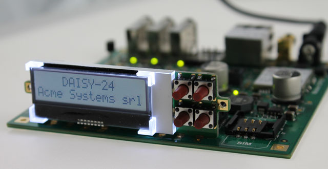
Daisy-24 - Front panel LCD with push buttons
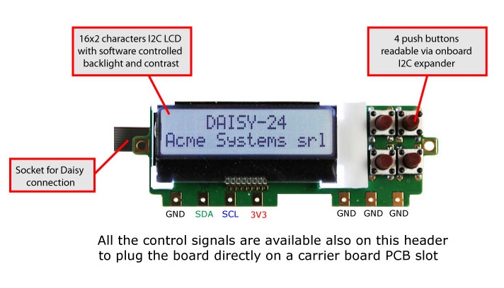
DAISY-24 can be soldered directly on the Terra Board PCB and used as its front panel display or plugged on a Daisy connector.

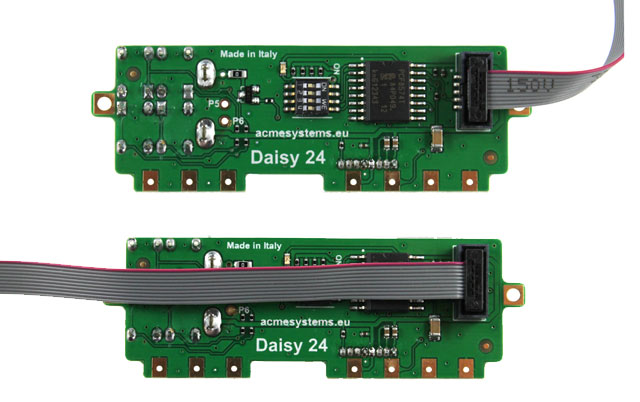
When soldered on the Terra board the flat cable is not required because all the signals are both on PCB pads (see below) and on Daisy connector.

If the flat cable is used an insertion key on the connector ensures to plug it in the right way.

Suitable class='acmetable' Daisy connectors
This is the list of suitable class='acmetable' Daisy connectors where are available the I2C bus signals to use with DAISY-24 module:
| Board | Daisy connector |
|---|---|
| TERRA and TERRA-M | D10 |
| TERRA and TERRA-M | D13 |
| TERRA and TERRA-M | D16 |
| TERRA | D17 |
| FOXG20 + DAISY-1 | D1 |
| FOXG20 + DAISY-1 | D6 |
| FOXG20 + DAISY-1 | D8 |
If you are using and Arietta G25 the pin to use on J4 are:
| Signal | Description | Arietta Pin # | Daisy 24 pin |
|---|---|---|---|
| 3V3 | Power out 3.3 volt DC | J4.5 | 3V3 |
| SDA0 | Data line bus 0 | J4.14 | SDA |
| SCL0 | Clock line bus 0 | J4.12 | SCL |
| GND | Ground | J4.9 | GND |
it is possible also to use the second I2C bus available on these pin
| Signal | Description | Arietta Pin # | Daisy 24 pin |
|---|---|---|---|
| 3V3 | Power out 3.3 volt DC | J4.5 | 3V3 |
| SDA1 | Data line bus 1 | J4.39 | SDA |
| SCL1 | Clock line bus 1 | J4.37 | SCL |
| GND | Ground | J4.9 | GND |
Code examples
Troubleshootings
The DAISY-24 uses two I2C addresses on I2C bus 0. One for the LCD and another one for the I2C I/O expander used to read the four push buttons and turn on the LCD backlight
The LCD address is fixed at 0x3E.
The I/O expander I2C address usually is 0x27 but could change to 0x3F for some batch of DAISY-24 which using a different chip version as listed below:
| Chip mounted | I2C address | How to use the ablib class |
|---|---|---|
| PCF8574T | 0x27 | ablib.Daisy24() |
| PCF8574AT | 0x3F | ablib.Daisy24(exp_address=0x27) |
It is possible to probe which is the address used with the
existI2Cdevice function available in ablib.py as shown in this
example:
Related links


