Interfacing a Hitachi HM55B compass module
written by Antonio GaleaHow to interface an electronic compass to the FOX Board in user space
The Hitachi HM55B Compass Module produced by Parallax is a dual-axis magnetic field sensor, that is, the electronic equivalent of a traditional compass.

Since it comes in a standard 6-pin DIP package and can be operated at 5V, interfacing it with our FOX Board is a snap: all that is required is some wiring.
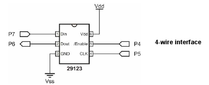
A falling edge (a transition from high to low) on /Enable pin will tell the chip to expect a command, that will be ended by a raising edge, again on /Enable. The commands are sent out serially one bit a time by raising Clock and then setting the required level on Dout pin. Same goes for reading from Din: raise Clock, read level, lower Clock.
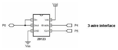
It is also possible to connect Dout and Din, and save one IO pin for connecting other hardware.
To obtain a measure of the magnetic field, you need to send a RESET followed by a START MEASURE command. Then, you loop asking for status until the device signals that the measurement is complete, at which point you can get the x,y data from Din as two 11 bit quantities.
Let's have a look at code to interface with this chip and read it's data.
#include <stdio.h>
#include <unistd.h>
#include <sys/ioctl.h>
#include <sys/poll.h>
#include <signal.h>
#include <fcntl.h>
#include <time.h>
#include <asm/etraxgpio.h>
#include <stdlib.h>

#define PORT_A 0
#define PORT_B 1
#define PORT_G 2

#define ENABLE_PORT PORT_G
#define ENABLE_PIN  (1<<5)
#define CLOCK_PORT  PORT_G
#define CLOCK_PIN   (1<<3)
#define DOUT_PORT   PORT_B
#define DOUT_PIN    (1<<6)
#define DIN_PORT    DOUT_PORT
#define DIN_PIN     DOUT_PIN

// Parallax commands
#define RESET   0x00
#define MEASURE 0x08
#define REPORT  0x0C
// Parallax constants
#define READY   0x0C
#define ERROR   0x03

#ifdef DEBUG
#define D(x) x
#else
#define D(x)
#endif

char *dev_names[3] = { "/dev/gpioa", "/dev/gpiob", "/dev/gpiog" };
int gpio_ports[3]  = { 0, 0, 0 };

/////////////////////////////////////////////////////////////////////////////////////
void delay(millis){ poll(NULL,0,millis); }

/////////////////////////////////////////////////////////////////////////////////////
void set(int port, unsigned char pin, unsigned char state){
 D(printf("set(port=%d,pin=%d,state=%d)\n",port,pin,state?1:0));
 ioctl(gpio_ports[port], _IO(ETRAXGPIO_IOCTYPE, (state? IO_SETBITS : IO_CLRBITS) ), pin);
}
void en (unsigned char state){ set(ENABLE_PORT,ENABLE_PIN,state); }
void clk(unsigned char state){ set(CLOCK_PORT,CLOCK_PIN,state); }
void out(unsigned char state){ set(DOUT_PORT,DOUT_PIN,state); }
unsigned char in(void){
 unsigned long value;
 ioctl(gpio_ports[DIN_PORT], _IO(ETRAXGPIO_IOCTYPE, IO_READ_INBITS),&value);
 value = (value&(DIN_PIN)) ? 1 : 0;
 D(printf("in()=%d\n",value));
 return value;
}
void shiftout(unsigned char data,unsigned char len){
 int i;
 unsigned long iomask = DOUT_PIN;
 ioctl(gpio_ports[DOUT_PORT], _IO(ETRAXGPIO_IOCTYPE, IO_SETGET_OUTPUT), &iomask);
 for(i=len-1;i>=0;i--){ // chip expects MSB first
  clk(1);
  out( (data & (1<<i)) );
  clk(0);
 }
}
void shiftin(unsigned int *data,unsigned char len){
 int i;
 unsigned long iomask = DIN_PIN;
 ioctl(gpio_ports[DIN_PORT], _IO(ETRAXGPIO_IOCTYPE, IO_SETGET_INPUT), &iomask);
 *data = 0;
 for(i=len-1;i>=0;i--){ // chip sends MSB first and after receiving clock
   clk(0);
   clk(1);
   *data += (in()<<i);
 }
}

/////////////////////////////////////////////////////////////////////////////////////
void measure(int *x, int *y){
 unsigned int status = 0;
 unsigned int negmask = 0xFFFFF800;

measure:
 en(0); clk(0);

 D(printf("sending RESET:\n"));
 en(1); en(0);
 shiftout(RESET,4);
 en(1);

 D(printf("sending MEASURE:\n"));
 en(1); en(0);
 shiftout(MEASURE,4);
 en(1);

 delay(40);

 do{
  D(printf("sending REPORT:\n"));
  en(1); en(0);
  shiftout(REPORT,4);
  D(printf("waiting for READY:\n"));
  clk(0);
  shiftin(&status,4);
  if(status==ERROR){
    printf("ADC overflow error - restarting.\n");
    en(1);
    goto measure;
  }
 }while(status!=READY);

 D(printf("reading measure data:\n"));
 shiftin(x,11);
 shiftin(y,11);
 en(1);

 if(*x & (1<<10)){ *x |= negmask; }
 if(*y & (1<<10)){ *y |= negmask; }

}

/////////////////////////////////////////////////////////////////////////////////////
void open_ports(void){
 int i;
 unsigned long iomask_out, iomask_in;
 for(i=0;i<3;i++){
   iomask_out=iomask_in=0;
   if(ENABLE_PORT == i) iomask_out |= ENABLE_PIN;
   if(CLOCK_PORT == i)  iomask_out |= CLOCK_PIN;
   if(DOUT_PORT == i)   iomask_out |= DOUT_PIN;
   if(DIN_PORT == i)    iomask_in  |= DIN_PIN;
   if(iomask_out||iomask_in){
    gpio_ports[i]=open(dev_names[i],O_RDWR);
    if(gpio_ports[i]<0){ printf("Error opening %s\n",dev_names[i]); exit(1); }
    D(printf("gpio_ports[%d]=%d\n",i,gpio_ports[i]));
   }
   if(iomask_out){
    ioctl(gpio_ports[i], _IO(ETRAXGPIO_IOCTYPE, IO_SETGET_OUTPUT), &iomask_out);
   }
   if(iomask_in){
    ioctl(gpio_ports[i], _IO(ETRAXGPIO_IOCTYPE, IO_SETGET_INPUT), &iomask_in);
   }
 }
 en(1); clk(0);
}

void close_ports_and_quit(int sig){
 int i;
 if(sig==SIGINT){
  D(printf("Got a SIGINT, bailing out.\n"));
  // stop
  en(0); clk(0); out(0);
  // close ports
  for(i=0;i<3;i++){ if(gpio_ports[i]) close(gpio_ports[i]); }
  exit(0);
 }
}

/////////////////////////////////////////////////////////////////////////////////////
int main(int argc, char *argv[]){
 int x=0,y=0;

 // start
 open_ports();

 // handle CTRL_C to shutdown cleanly
 signal(SIGINT,close_ports_and_quit);

 // take measures until CTRL_C
 while(1){
  measure(&x,&y);
  printf("x=%d, y=%d\n",x,y);
 }

 return 0;
}
The main() function is pretty simple. Function open_ports() takes care of opening
the needed IO ports and setting the pins directions; the #define directives inform it about
which ports and pins will be needed.
In this case, we are using a 3-wire configuration with the following pins:
| /Enable | OG5 |
|---|---|
| Clock | OG3 |
| Din,Dout | PB6 |
The core of our implementation is, of course, inside function measure().
Here the only peculiarity is how we take care of negative values for x and y, which are 11 bit quantities inside a 32 bit integer storage: if their sign bit (bit 10) is set, we need to fill with 1s the bits from 11 to 31.
Finally, here's the implementation for the functions that really drive our pins.
This is the Makefile for compiling this code:
#AXIS_BUILDTYPE   = cris-axis-linux-gnuuclibc
#AXIS_BUILDTYPE   = cris-axis-linux-gnu
AXIS_USABLE_LIBS = UCLIBC GLIBC
include $(AXIS_TOP_DIR)/tools/build/Rules.axis

SRCS   = parallax.c
PROGS  = $(SRCS:.c=)

#CFLAGS = -DDEBUG

all: $(PROGS)
	cris-strip $(PROGS)

clean:
	rm -f $(PROGS) *.o core
To compile create a directory parallax inside the dir apps. Then copy inside it the source code parallax.c and the Makefile. Move into apps/parallax directory and type:
# make cris-axis-linux-gnu
# make
Uncomment the CFLAGS line inside Makefile to obtain a debug version of the program.