Using the GPRS section on Terra board
A Quectel M95 quad band GPRS module is mounted on TERRA-M board. It comunicates with the Aria G25 Linux module through a serial port mapped to /dev/ttyS1. All the modem function can be controlled using the Quectel AT commands set.
Before sending any AT message to the modem it's requested to turn-on the power section that provides the 4.4 volt to the pin VIN of the modem module.
At startup this section is in off state. To turn it on we have to set the Aria G25 W10 line (Atmel PA23 GPIO line) as output and put it in hi-state using these commands:
echo 23 > /sys/class/gpio/export
echo out > /sys/class/gpio/pioA23/direction
echo 1 > /sys/class/gpio/pioA23/value
The green led labeled 4V4 will turn on.
In this state we have to send an hi pulse to the modem PWRKEY line. This pin is wired on Aria G25 E10 gpio (Atmel PC30 GPIO line).
Configure this pin as output and send a 1 second hi pulse using these commands:
echo 94 > /sys/class/gpio/export
echo out > /sys/class/gpio/pioC30/direction
echo 1 > /sys/class/gpio/pioC30/value
sleep 1
echo 0 > /sys/class/gpio/pioC30/value
Check the green led labeled GSM, it will start to blink. If a GSM antenna is plugged and a valid SIM in inserted the blink will become to be slower after a while to indicate that the modem is registered to the GSM network.
In this state it is possible to send the AT commands to the serial port /dev/ttyS1.
GPRS link examples
Wirings between the Quectel M95 quad band GPRS modem and the Aria G25 module
Following is the pinout of Quectel modem:
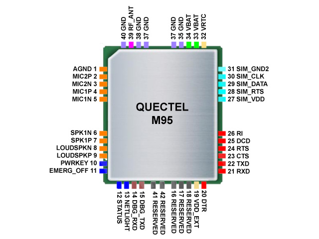
and this is the wirings between it and the Aria G25:
| Quectel pin # | I/O | Quectel signal | Aria G25 pin # | Aria G25 signal | Notes |
|---|---|---|---|---|---|
| 21 | I | RXD | S23 (PA0) | /dev/ttyS1 TXD0 | |
| 22 | O | TXD | S22 (PA1) | /dev/ttyS1 RXD0 | |
| 23 | I | CTS | S20 (PA3) | /dev/ttyS1 CTS0 | |
| 24 | O | RTS | S21 (PA2) | /dev/ttyS1 RTS0 | |
| 10 | I | PWRKEY | E10 (PC30) | GPIO (94) | Normal state Low |
| 11 | I | EMERG_OFF | E11 (PC31) | GPIO (95) | Normal state Low |
| 12 | O | STATUS | N6 (PC4) | GPIO (68) | |
| Power supply | W10 (PA23) | GPIO (23) | 0=Power off, 1=Power on |
Please note that Ring Indicator (RI) and Data Carrier Detect (DCD) are not connected to the Aria pins.
Send an SMS
Install minicom:
apt-get update
apt-get install minicom
Insert an enabled SIM with teh PIN request disabled then turn ON the modem and launch minicom:
minicom -s
Select "Serial port setup" then:
┌───────────────────────────────────────────────────────────────────────┐
│ A -    Serial Device      : /dev/ttyS1                                │
│ B - Lockfile Location     : /var/lock                                 │
│ C -   Callin Program      :                                           │
│ D -  Callout Program      :                                           │
│ E -    Bps/Par/Bits       : 19200 8N1                                 │
│ F - Hardware Flow Control : Yes                                       │
│ G - Software Flow Control : No                                        │
│                                                                       │
│    Change which setting?                                              │
└───────────────────────────────────────────────────────────────────────┘
go back to the termianl screen (Exit) and type:
AT+CMGF=1 (enter)
OK
AT+CMGS="+393460624344" (enter)
>Hello (ctrl-z)

+CMGS: 12
OK