DAISY-19 - 4 channels industrial range optoisolated output (0-48 Volt)
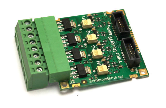
The board is equipped with four leds to check each output state. When a led is on its associated output is active (the MOSFET is conducting).
Features
- 4 channels output stage driven by MOSFETs
- Drain-source voltage max: 48 Volt
- Continuous source current: 3.5 A
- Isolation voltage: 2500 Vrms (max)
The daisy connectors where to plug this board are:
| Daisy Connector |
|---|
| FOX D2 |
| FOX D5 |
| TERRA D11 |
| TERRA D12 |
On the FOX Board G20 is requested a Daisy-1 adapter.
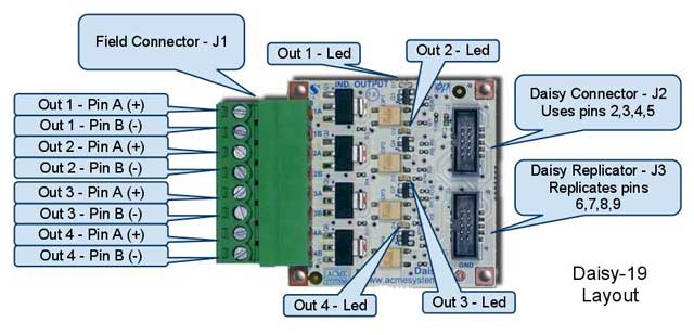
General Layout
The following picture shows Daisy-19 connectors and monitoring LEDs.
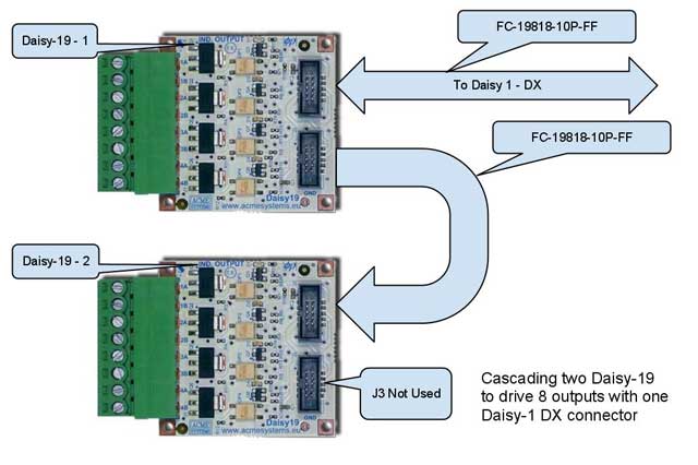
Connecting to a Daisy-1
Up to 2 Daisy-19 boards can be connected to the same Daisy-1 connector by means of the Replicator connector J3. So full use of all I/O pins on a single Daisy-1 connector is made. This applies to Daisy-1 connectors: D2, D3, D5 provided all pins are set as GPIO.
Daisy-19 cascading feature is illustrated by the following picture :
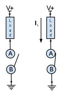
Using one board to drive loads in more than one way
Due to the "floating" optoisolated N channel MOSFETs, the Daisy-19 is able to handle different kinds of loads and drive configurations with single and dual power supply :
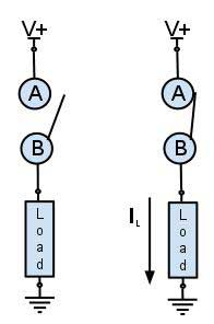
Sink mode (aka NPN)
Up to 4 loads can be driven in this configuration.
Source mode (aka PNP)
Up to 4 loads can be driven in this configuration.
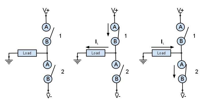
Half H bridge mode
Up to 2 loads can be driven in this configuration.
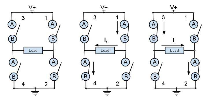
Full H bridge mode
Just 1 load can be driven in this configuration.
Mixed modes are easily handled by Daisy-19 as shown in the following case list:
Case A :
- Output 1 : Sink mode +24V
- Output 2 : Source mode +5V
- Output 3 : Source mode +12V
- Output 4 : Sink mode +5V
Case B :
- Output 1 : Sink mode +24V
- Output 2: Source mode +5V
- Outputs 3 & 4 : Half Bridge +/-12V
Case C :
- Outputs 1 & 2 : Half Bridge +/-24V
- Outputs 3 & 4 : Half Bridge +/-12V
Daisy connector pinout (MAIN)
| Pin # | Signal |
|-------|--------|
| 1     | 3V3    |
| 2     | A      |
| 3     | B      |
| 4     | C      |
| 5     | D      |
| 6     | ext A  |
| 7     | ext B  |
| 8     | ext C  |
| 9     | ext D  |
| 10    | GND    |
Schematics, datasheets and related links
- DAISY-19 Schematic
- ZXMN6A09 - 60V SOT223 N-channel enhancement mode MOSFET datasheet
- TLP190B Photocoupler datasheet
- Daisy modules and other boards available